Whether it comes to hardware debugging or simulation, we often deal with chip driver configurations. For example, the DDR controller has various driver settings, such as 34 ohms, 40 ohms, or other resistance values, as well as fast, mid, or slow drive modes. The former mainly affects the output voltage level, where lower internal resistance results in a higher output level. The latter refers to the slope of the signal transition — a fast drive produces steeper rising and falling edges, while a slow drive makes them more gradual. In general, "driving" refers to one or both of these aspects.
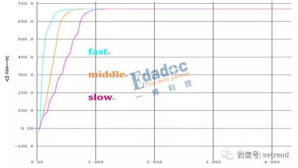
For instance, when a DDR controller is connected to a 50-ohm load, the output waveform varies depending on the driver configuration. The difference between drivers at a fast slope can be seen in the variation of the output level. Here's an image showing the waveform differences:

If both drivers have the same 40-ohm internal resistance but different slope settings, their waveforms will look similar in amplitude but differ in the steepness of the rising edge. This is clearly visible in the following image:
Now, you might think that stronger driving means higher amplitude and steeper edges, which is always better. But this isn't necessarily true. A smaller internal resistance doesn’t always mean better performance, and a steeper edge isn’t always ideal. It depends on the signal topology, especially for address signals, as discussed in a previous article:
To understand the impact of slope, let’s fix the driver to 40 ohms and observe the eye diagram:
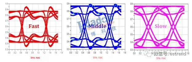
From the eye diagrams, the faster transitions may appear larger, but they result in a narrower eye width. The middle slope seems to offer the best balance.
Next, let’s fix the slope to fast and vary the internal resistance. The resulting eye diagram is as follows:
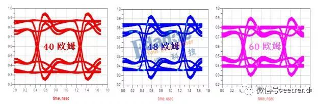
As shown, varying the internal resistance only changes the voltage level when the slope is fixed. There’s little improvement in terms of overshoot or undershoot.
In the case of address signals, a steeper edge does lead to better signal quality. However, this is because the signal is prone to multiple reflections, which become more complex. As shown below, the frequency domain analysis (return loss and insertion loss) reveals significant reflection across a wide frequency range.
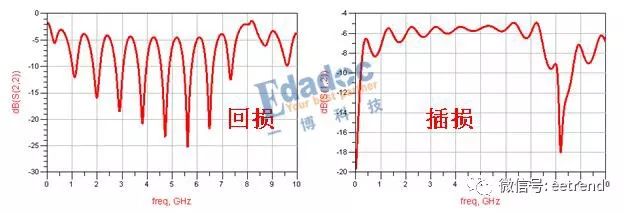
The steeper the edge, the more high-frequency energy is present, making the system more sensitive to reflections. This leads to oscillations in the time domain. To reduce this, choosing a slightly slower drive can help filter out some of the reflection peaks, thus reducing the oscillation. However, if the drive is too slow, it can negatively affect the timing window, leading to potential signal integrity issues. Therefore, finding the right balance is crucial.
Radiators, essential yes, but sometimes they`re pretty ugly. I can say this from personal experience, as a discoloured radiator sits in my hallway bringing down the decor. Faced with the option of replacing it at great cost, I`m now thinking a splash of paint might be the better option.
That theory is backed up by seeing this bold painted radiator transformation!
Painted Radiator,Finned Painted Radiator,Distribution Finned Painted Radiator,Painted Transformer Cooling Radiator
Shenyang Tiantong Electricity Co., Ltd. , https://www.ttradiator.com